


What is Piping and Instrumentation Diagram (P&ID)?


In the process industry, effective communication and understanding of complex systems are paramount, and this is where Piping and Instrumentation Diagrams (P&IDs) come into play. A P&ID serves as a vital blueprint that illustrates the intricate relationships between piping, equipment, instrumentation, and control systems within a facility.
By providing a detailed visual representation of the physical sequence of components and their interconnections, P&IDs enable operators and engineers to efficiently manage, maintain, and modify process systems.
This article delves into the significance of P&IDs, their essential components, and the critical role they play in ensuring safe and efficient operations in industrial settings.
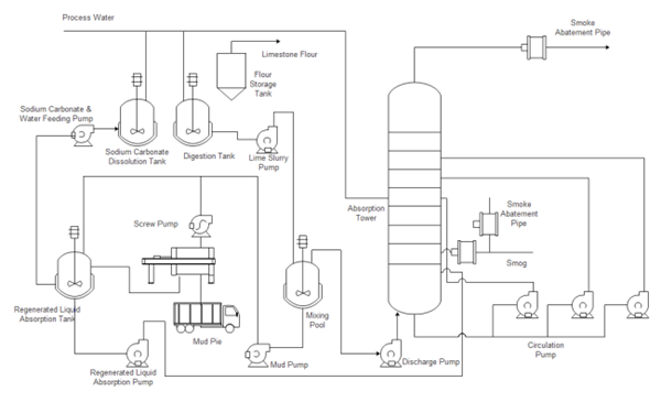
A piping and instrumentation diagram (P&ID) is a drawing in the process industry. A P&ID shows all piping, including the “physical sequence of branches, reducers, valves, equipment, instrumentation and control interlocks.”
A P&ID is used to operate the process system, since it shows the piping of the process flow along with the installed equipment and instrumentation.
P & IDs play a key role in maintaining and modifying the process they describe, because it is important to demonstrate the physical sequence of equipment and systems, including how these systems connect. In terms of processing facilities, a P&ID is a visual representation of key piping and instrument details, control and shutdown schemes, safety and regulatory requirements, and basic start-up and operational information.
The following list outlines the items that typically are found in a P&ID:
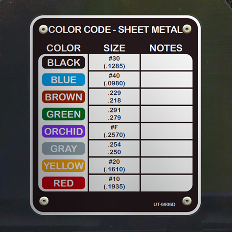
As you can imagine, a P&ID involves various symbols to represent all of the included parts, components, and information. Their symbology is defined on separate drawings referred to as “lead sheets” or “legend sheets.”
Lead sheets should be customized to each company’s process plants, though in general, the P&IDs are based on a core set of standard symbols and notations. The most important part of the lead sheets is that they are organized logically so that it is possible to easily locate the symbols and tags.
While it’s a good practice to have lead sheets for the major equipment in a factory, it may not be necessary because this major equipment already should be tagged and named with general specifications for identification purposes.
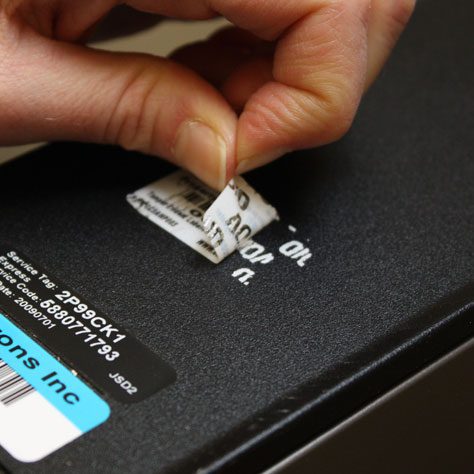
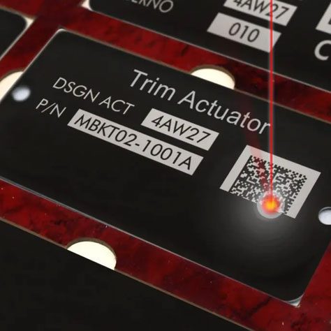
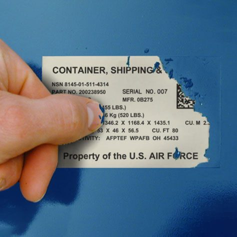
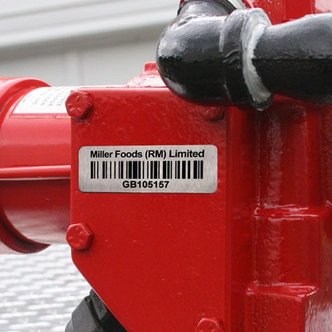
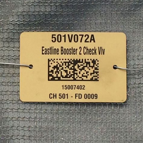
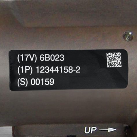
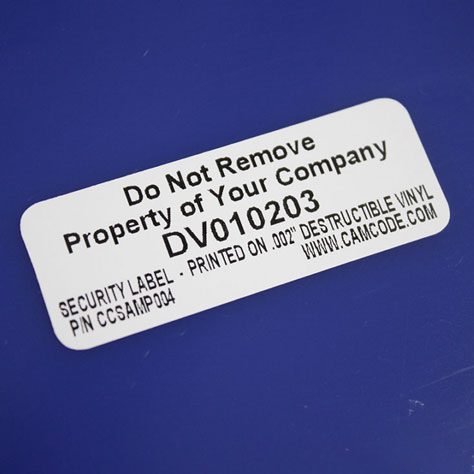
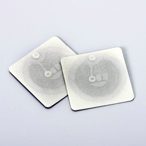
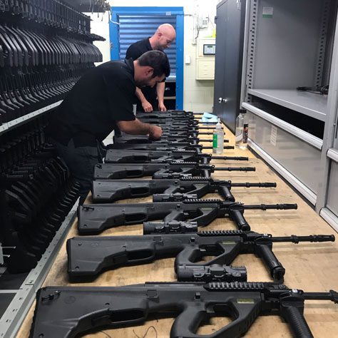
Because a P&ID contains such important information, it is critical to the workings of the process industry that the process plant apply tags or labels to keep track of all of the equipment, piping, valves, devices, and more. Those labels must match the symbology and should not fail, so that the plant’s operations run smoothly and efficiently.
That’s why the unique identifiers involved in the P&ID, tagging, and labeling process are critical. In fact, there are three main reasons that the tagging should be done correctly:
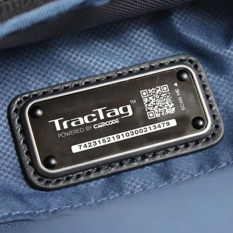
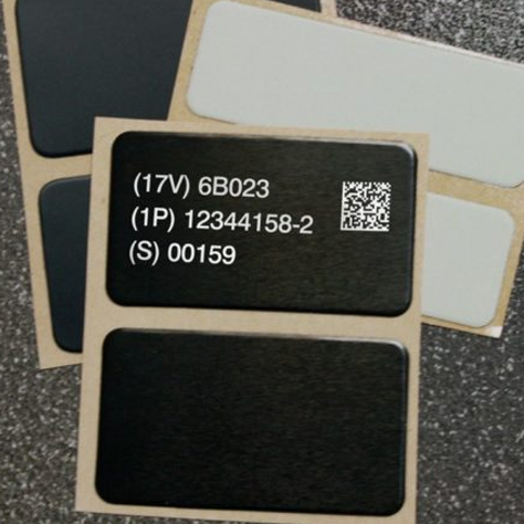
Using a numeric-only system for tagging equipment is the best way for process industries to avoid the problems with labeling by abbreviated names. Structured tag systems are more intuitive for every team that deals with the equipment, including developers, operators, and maintenance. The equipment tag format should be a series of three numbers, beginning with an area number, followed by an equipment type code, and then ending with a unique sequence number.
Piping and Instrumentation Diagrams are essential tools in the process industry, providing a comprehensive visual representation of complex systems. Their importance in facilitating clear communication, ensuring safety, and supporting efficient operations cannot be overstated.
As technology advances, P&IDs may evolve, but their fundamental role in bridging conceptual design and practical implementation will remain crucial. Mastering P&IDs is a vital skill for industry professionals, contributing to safer, more efficient operations and supporting continuous improvement initiatives.
In essence, P&IDs exemplify the power of visual communication in engineering, serving as the backbone of effective system management in the process industry.
Our sales engineers are experts in automatic asset tracking, tagging and identification,a nd can answer all your questions. Get in touch now.
Lets Talk ›Enter your information and get a free checklist of the top questions to answer and tips to plan a successful asset tagging project for any asset management or tracking system implementation.